What to know
- Pipe logistics simulations focus on building a valid pipeline route between given endpoints using the correct fittings.
- Crossing two lines usually requires a bridge-type fitting; direct intersections often fail the logic check.
- Splitting and merging should be done with dedicated splitter/converger fittings rather than ad-hoc junctions.
- If the route “looks connected” but fails, the issue is usually at the fitting ports or a single mis-snapped segment.
In Arknights: Endfield, Pipe Logistics Simulation is essentially a routing puzzle. The fastest clears come from planning the functional points first (cross, split, merge, restrict), then filling in straight pipe segments.
Reference table for common pipe parts
| Part / concept | Purpose | When to use it |
|---|---|---|
| Straight pipe segments | Basic connectivity | Use to connect between functional fittings with minimal bends |
| Elbows/turn segments | Change direction | Use only where needed; extra turns make mistakes harder to spot |
| Pipe bridge | Cross one pipe over another | Use when two routes must cross without interacting |
| Pipe splitter | Split one input into 2–3 outputs | Use when one source must feed multiple destinations |
| Pipe converger (merge) | Merge up to 3 inputs into one output | Use when multiple sources must feed one destination line |
| Control/restriction node (if available in the simulation) | Restrict what flows through | Use when the simulation expects a “controlled” line rather than free mixing |
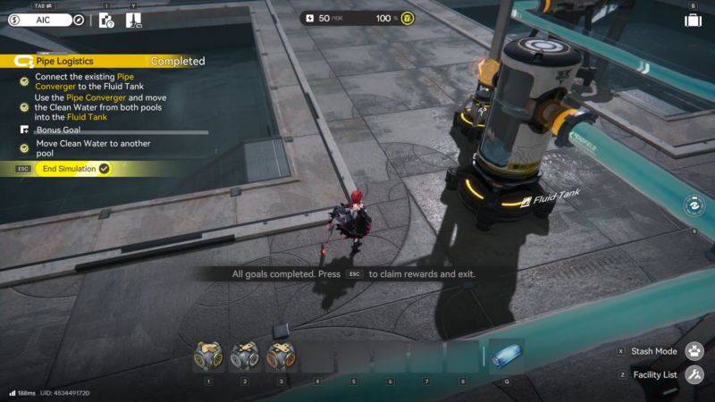
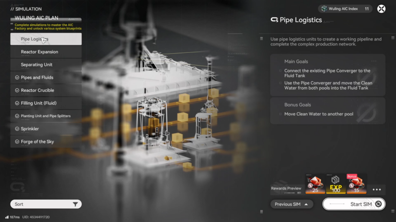
How to clear Pipe Logistics Simulation
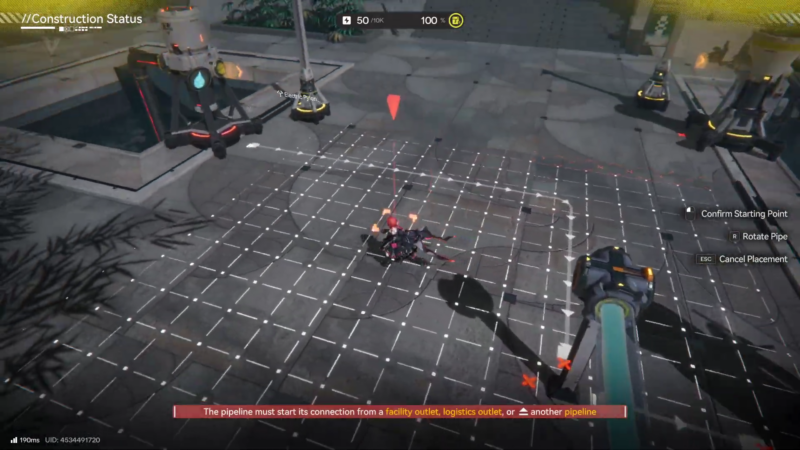
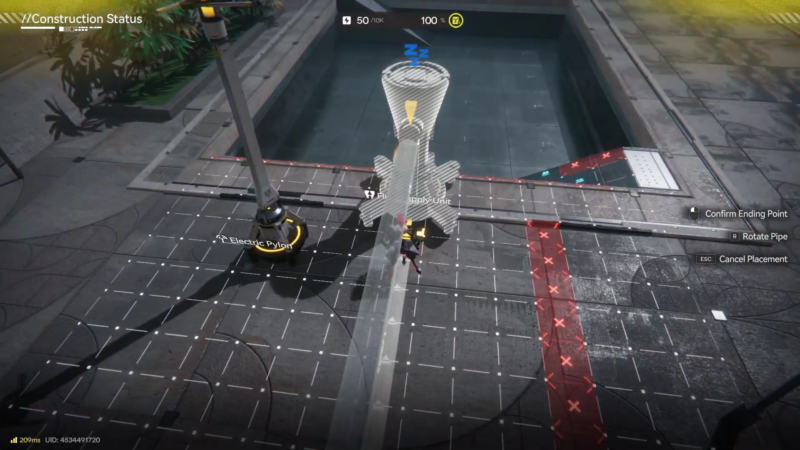
Step 1: Survey all endpoints before building
Open the simulation and pause before placing anything. Identify every source output and every destination intake, then decide whether the final design needs a single main line with branches, or multiple separate lines.
Step 2: Plan the functional points (cross, split, merge, restrict)
Mark “functional points” on the grid:
- Any place two lines must cross → reserve space for a pipe bridge.
- Any place one line must feed two/three endpoints → reserve space for a pipe splitter.
- Any place two/three sources must combine → reserve space for a pipe converger.
- Any place a restriction/control piece is required → reserve space early along the intended main route.
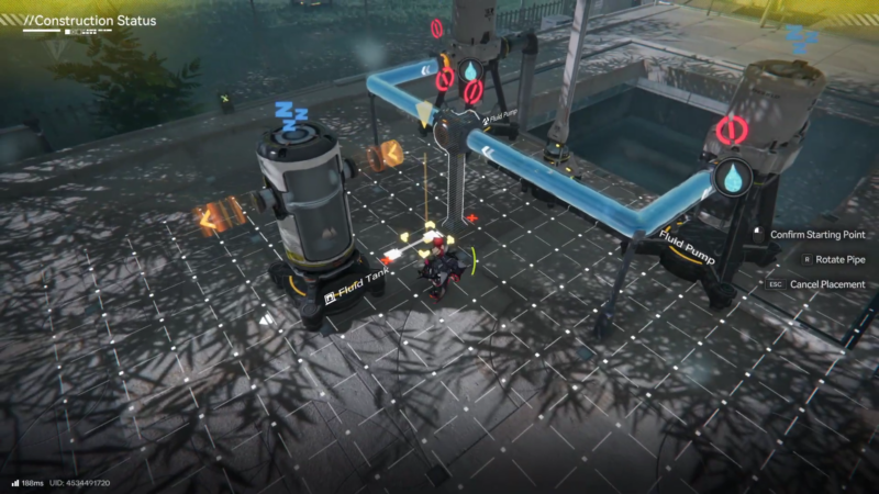
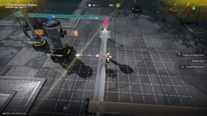
Step 3: Place fittings first and confirm orientation

Place the key fittings first (bridge/splitter/converger/control). Ensure each fitting is oriented correctly so inputs and outputs face the intended directions.
Step 4: Connect each source to the nearest fitting input with clean runs
Connect sources to their nearest fitting inputs using the simplest paths possible:
- Prefer straight lines.
- Avoid weaving around unless the layout forces it.
- Do not “tee” into a line unless the simulation explicitly allows a basic junction (most simulations expect the dedicated splitter/converger).
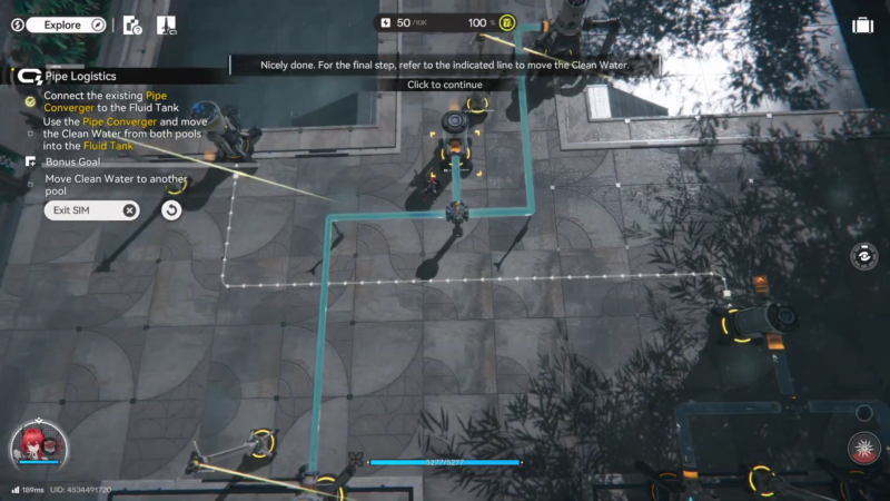
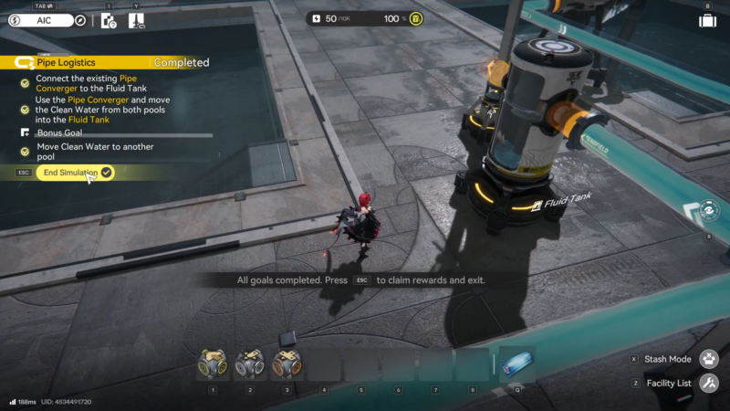
Step 5: Build the trunk line from the final merge (or source) to the destination
Build the main output route from the final merge point (or the source, if no merge exists) to the destination intake. Keep this “trunk” route clean and easy to visually audit.
Step 6: Handle crossings with a proper bridge (no intersections)
If the layout requires a crossing, complete the bridge crossing now and re-check that the two routes remain independent (no accidental snaps to the wrong port near the crossing).
Step 7: Add branches one at a time from the splitter outputs
If the layout requires branching, connect splitter outputs to each destination one at a time. After each branch, quickly scan the branch’s first 2–3 tiles near the splitter to confirm it snapped to the correct output port.
Step 8: Merge flows only through the converger inputs
If the layout requires combining flows, connect each source line into a separate converger input. Ensure none of the sources merge together before reaching the converger.
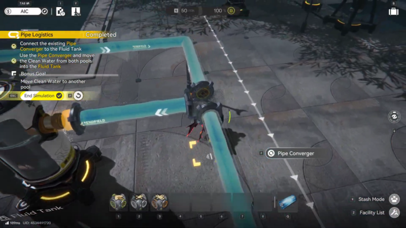
Step 9: Run the check and pinpoint the first failure location
Run the simulation check (or start flow) and watch for the first point where flow stops or the validation fails. Do not rebuild everything—start debugging at the nearest fitting.
Troubleshoot using this order (fastest to slowest):
- Rebuild 1–3 pipe tiles directly adjacent to each fitting port (most failures are a single wrong snap).
- Verify the bridge crossing is actually a bridge and not an intersection.
- Verify split branches originate from a splitter output, not from a mid-line junction.
- Verify merges only occur through a converger, not by connecting lines together before the converger.
- If a control/restriction node exists, confirm it sits on the intended trunk line (not on a dead-end branch).
Common failure points and fixes
| Symptom | Likely cause | Fix |
|---|---|---|
| “Looks connected” but fails validation | One segment snapped to the wrong port on a fitting | Delete and rebuild the 1–3 tiles touching the fitting |
| Flow stops right at a crossing | No bridge used, or bridge oriented incorrectly | Replace with a bridge and rebuild the tiles entering/exiting it |
| Only one destination receives flow | Split done with a junction instead of a splitter | Replace junction area with a dedicated splitter |
| Flow backs up or never reaches destination after combining | Lines merged before the converger or converger output not connected | Route each source into separate converger inputs, then rebuild the output line |
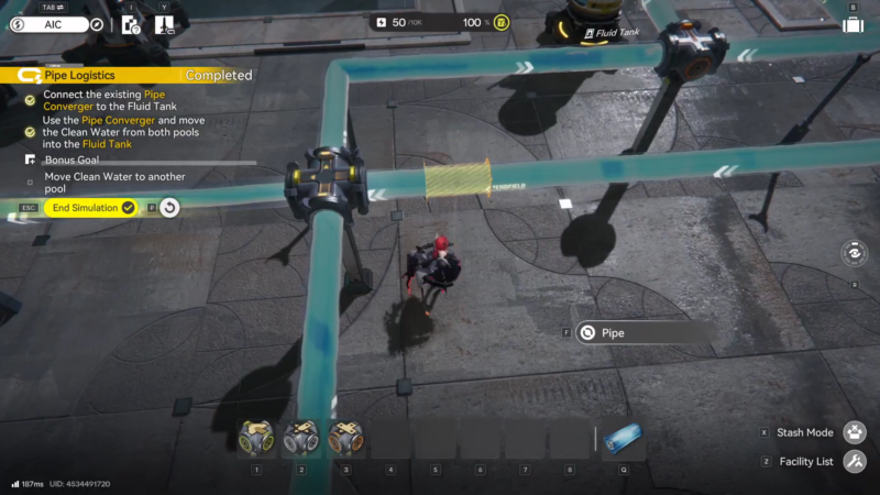
Pipe Logistics simulation can be easy!
Most clears become simple when the build is treated like a diagram: crossings are bridges, branching is splitters, combining is convergers, and control pieces go on the trunk line early. Once those anchors are correct, the rest is just clean pipe runs.